Ფილტრის პლისები წარმოადგენს თანამედროვე ფილტრაციის სისტემებში ერთ-ერთ ყველაზე მნიშვნელოვან დიზაინის ელემენტს, რომელიც საბოლოოდ განსაზღვრავს ფილტრის სიბერკეტის ხარისხს და აერონაკადის საკმარისი დონის შენარჩუნების შესაძლებლობას. ფილტრის პლისებში გეომეტრიული კონფიგურაცია, სიღრმე, სივრცის ნაკრების ნიმუშები და მასალის დაძაბულობა პირდაპირ ახდენს გავლენას როგორც მიმდინარე სამუშაო მახასიათებლებზე, ასევე ფილტრაციის მოწყობილობის გრძელვადიან სამუშაო სიმტკიცეზე სამრეწველო, კომერციულ და საყოფაცხოვრო გამოყენებებში.
Ფილტრის კრავის დიზაინსა და მისი ეფექტურობას შორის კავშირის გაგება მოითხოვს ზედაპირის ფართობის გაფართოების, წნევის ვარდნის მახასიათებლების და სტრუქტურული მტკიცებულების ერთობლივი მოქმედების შესწავლას, რათა შეიქმნას ოპტიმალური ფილტრაციის პირობები. ფილტრის კრავის ინჟინერული დაგეგმვის სახე გავლენას ახდენს ყველაფერზე — ნაკლებად მოცული ნაკრების დაჭერის ეფექტურობიდან მოხსნის ინტერვალებამდე, რაც საშენობის მენეჯერებსა და ინჟინერებს აუცილებლად აუცილებელს ხდის ამ ერთმანეთთან დაკავშირებული სამუშაო მახასიათებლების გაგებას ფილტრაციის სისტემების არჩევისა და მათი მოვლის დროს.
Ფილტრის კრავის გეომეტრიის მეშვეობით ზედაპირის ფართობის გაძლიერება
Კრავის სიღრმის გავლენა ფილტრაციის ზედაპირზე
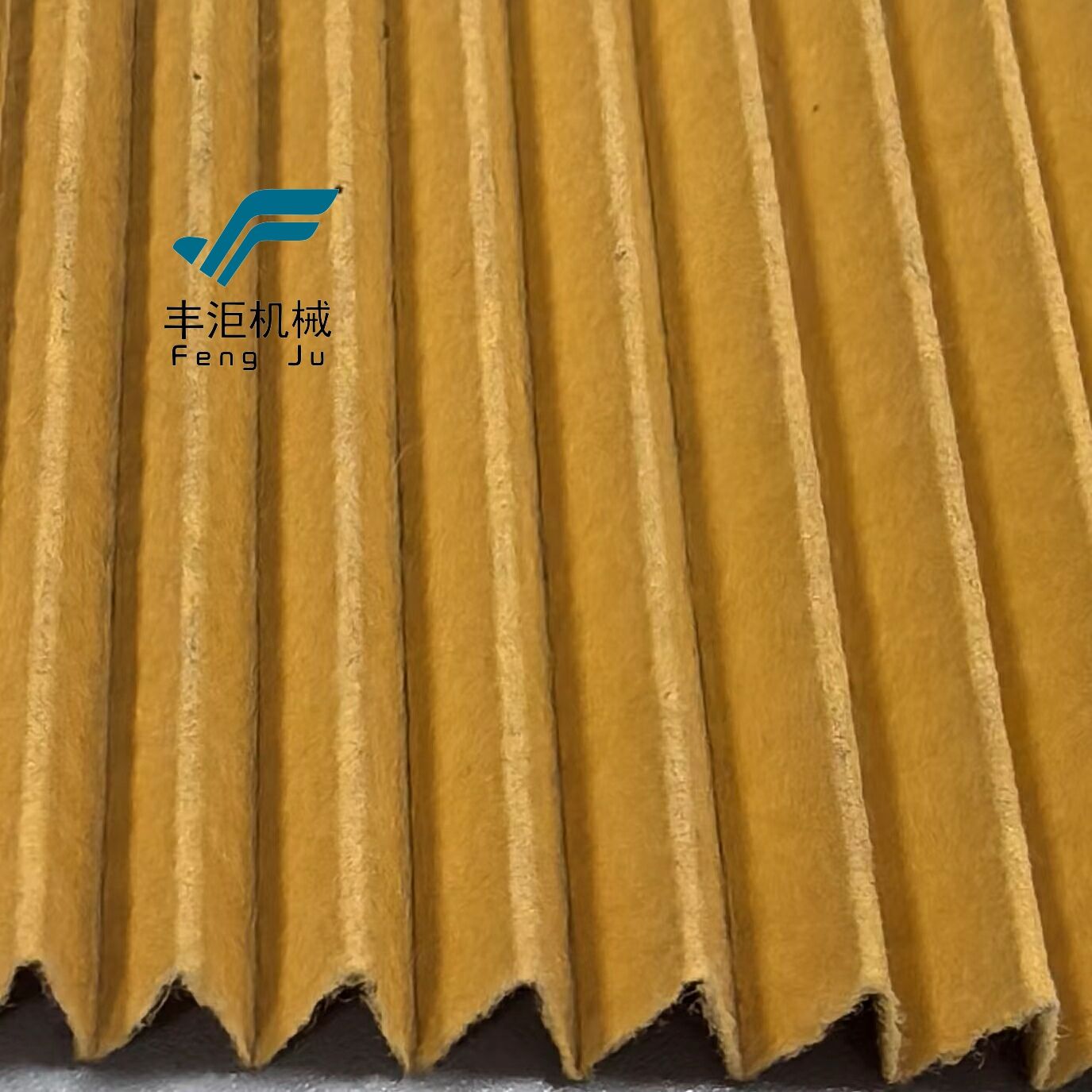
Ინდივიდუალური საფილტრო ნაკეცების სიღრმე პირდაპირ განსაზღვრავს ნაკეცების კონფიგურაციაში ხელმისაწვდომ საერთო ზედაპირს ნაკლებად მყოფი ნაკრების დაჭერისთვის, სადაც უფრო ღრმა ნაკეცები იძლევა ექსპონენციალურად მეტ საფილტრო მასალას იგივე საყრდენი განზომილებების рамკაში. სტანდარტული ზედაპირული ნაკეცები ჩვეულებრივ 3–5 ჯერ მეტ ზედაპირს იძლევა ბრტყელი ფილტრების შედარებით, ხოლო ღრმა ნაკეცების დიზაინი შეიძლება მიაღწიოს 8–12 ჯერ მეტ ზედაპირს, რაც დრამატულად აუმჯობესებს ფილტრის შესაძლებლობას მაღალი ნაკრების ტვირთის მოსახსნელად გამოყენების დროს ადრეული დაბლოკვის გარეშე.
Ღრმა ფილტრების მოქსოვის საშუალებით შესაძლებელია მტვრის შენახვის უფრო დიდი უნარი, რადგან ნაწილაკები უფრო დიდ მედიის ზედაპირზე ნაწილდება, რაც ხელს უშლის სწრაფად დაგროვებას ლოკალიზებულ ადგილებში, რაც სხვაგვარად გამოიწვევს წნევის ვარდნის მწვერვალებს და ეს გაფართოებული ზედაპირის ფართობი ასევე საშუალებას იძლევა გამოიყენოს უფრო ეფექტური მასალები, რომლებიც სხვაგვარად შეიძლება წარმოქმნას მიუღებელი წნევის ვარდნა ბრტყელ კონფიგურაციებში, რაც ინჟინრებს საშუალებას აძლევს განსაზღვრონ HEPA ან ULPA ხარისხის ფილტრაცია
Ფლეტრის სიღრმისა და ზედაპირის ფართობის გეომეტრიული კავშირი მიჰყვება მოსალოდნელ მათემატიკურ პრინციპებს, რაც საშუალებას იძლევა ზუსტი გამოთვლები ოპტიმიზაციისათვის ფილტრის ფლეტრების დიზაინების მიხედვით სპეციფიკური მოთხოვნ ინჟინრები შეუძლიათ განსაზღვრონ იდეალური ფლაკონის სიღრმის გათვალისწინებით ისეთი ფაქტორების, როგორიცაა ხელმისაწვდომი სივრცის შეზღუდვები, მიზნობრივი ეფექტურობის დონე, მოსალოდნელი ნაწილაკების დატვირთვის სიჩქარე და წნევის წონის მიღების დასაშვები ზ
Ფილტრების პლეტების შორის მანძილების განაწილების ოპტიმიზაცია
Ფილტრების პლეტების სისტემებში ცალკეული პლეტების შორის სწორი მანძილების განაწილება უზრუნველყოფს ჰაერის განაწილების ერთგვაროვნებას მთლიანად ფილტრაციის მედიის ზედაპირზე, რაც თავიდან აიცილებს ასე წოდებულ ჩანელების ეფექტს, რომელიც შეიძლება შეამციროს საერთო ფილტრაციის ეფექტურობა. ძალიან ხშირი პლეტების მანძილების განაწილება ქმნის შეზღუდულ ჰაერის გზებს, რაც იძულებს ჰაერს გადაადგილდეს უფრო მისაღები გზებით, ხოლო ჭარბად გაშლილი მანძილების განაწილება ამცირებს საერთო ზედაპირის სარგებლიანობას და შეიძლება ნაკლებად ეფექტურად შეაჩეროს ნაკრებები, რაც შეიძლება სრულიად გამორიცხოს ფილტრაციის ზონების გამოყენება.
Ფილტრების პლეტების საუკეთესო მანძილების განაწილება დამოკიდებულია ფილტრაციის მედიის სისქეზე, მის სიმტკიცეზე და მოსალოდნელ ექსპლუატაციურ პირობებზე, ხოლო უმეტესობა სამრეწველო გამოყენებაში მოითხოვს პლეტების სიღრმის მიმართ 1:2-დან 1:3-მდე მანძილების განაწილების შეფარდებას. ეს მანძილების განაწილება საშუალებას აძლევს საკმარისი ჰაერის მოძრაობის უზრუნველყოფას პლეტებს შორის, ამავე დროს არ არღვევს სტრუქტურულ მტკიცებულებას სხვადასხვა წნევის პირობებში და თავიდან აიცილებს პლეტების ჩამოვარდნას, რაც შეიძლება შეამციროს ფილტრაციის ეფექტურობა.
Სწრაფვარი ფილტრების წარმოების განვითარებული ტექნიკები ახლა იყენებს ცვალებად მანძილებს, რომლებიც ოპტიმიზაციას ახდენენ ჰაერის ნაკადს კომპიუტერული სითხის დინამიკის მოდელირების საფუძველზე, რაც უზრუნველყოფს ხელმისაწვდომი ფილტრაციის მედიის ზედაპირის მაქსიმალურ გამოყენებას და წნევის კარგვის მინიმიზაციას. ეს სირთულის მქონე მანძილების დიზაინი შეიძლება გააუმჯობესოს ფილტრის სრული ეფექტურობა 15–25%-ით ერთნაირი მანძილების შედარებით, განსაკუთრებით მაღალი სიჩქარის მოდელებში, სადაც ჰაერის ნაკადის ერთნაირობა განსაკუთრებით მნიშვნელოვანი ხდება.
Წნევის კარგვის მახასიათებლები სწრაფვარი ფილტრების სისტემებში
Საწყისი წნევის კარგვის განხილვა
Საფილტრო პლეტირების სისტემებში საწყისი წნევის დაკლება ძალზე მჭიდროდ არის დაკავშირებული პლეტების გეომეტრიასთან, რადგან უფრო ღრმა პლეტები საერთოდ ქმნის ნაკლებ საწყის წინააღმდეგობას ზედაპირის ფართობის გაზრდის და ფილტრაციის მედიაზე მოქმედების სიჩქარის შემცირების გამო. თუმცა, პლეტების დიზაინსა და წნევის დაკლებას შორის კავშირი საკმაოდ რთულია, რადგან პლეტის წვეროს რადიუსი, მხარდაჭერის სტრუქტურები და მედიის გამტარობა ყველა ერთად წვლილი აწვდის საერთო წინააღმდეგობის მახასიათებლებში.
Კარგად შემუშავებული საფილტრო პლეტირები მოიცავს გრადიენტულ გადასვლებსა და პლეტების წვეროებში გლუვ მრუდებს ტურბულენტობისა და წნევის კორექციის მინიმიზაციის მიზნით, ხოლო ცუდად შემუშავებული პლეტები — მაგალითად, მაგრად გადახვეული კენტებით ან არასაკმარისი მხარდაჭერით — შეიძლება შექმნას მნიშვნელოვანი წინააღმდეგობა უკვე ახალი მდგომარეობაშიც. მწარმოებლის სიზუსტე ფილტრის შეკუმშვა პირდაპირ აისახება ამ საწყის წნევის მახასიათებლებზე, რაც საჭიროებს წარმოების დროს ხარისხის კონტროლს, რათა საფილტრო ბათქების მთელ სერიაში მივიღოთ სტაბილური სამუშაო მახასიათებლები.
Ინჟინრებს უნდა შეაწონონ მაქსიმალური ზედაპირის ფართობის მიღების სურვილი და კარკასის განზომილებებითა და დასაშვები წნევის ვარდნით განპირობებული პრაქტიკული შეზღუდვები, რაც ხშირად მოითხოვს იტერაციულ დიზაინის პროცესებს კონკრეტული მიზნებისთვის ფილტრის პლეტირების კონფიგურაციების ოპტიმიზაციის მიზნით. საწყისი წნევის ვარდნა საშუალებას აძლევს ფილტრის შესრულების მონიტორინგს დროთა განმავლობაში და წნევის სხვაობის გაზომვების საფუძველზე შესაბამისი ჩანაცვლების გრაფიკის დადგენას.
Წნევის შესრულებაზე პროგრესიული ტვირთვის ეფექტები
Როგორც ნაკრები იკრებება ფილტრის პლეტირების სტრუქტურებში, წნევის ვარდნა იზრდება წნარი ნაკრების გეომეტრიასა და ნაკრების მახასიათებლებზე დამოკიდებული წინასწარ განსაზღვრული ნაკრების მიხედვით. ღრმა პლეტირები საკმარისი სივრცით ჩვეულებრივ აჩვენებენ ნელა მატულობას წნევის ვარდნაში, რაც ფილტრებს საშუალებას აძლევს გრძელი ხანის განმავლობაში ეფექტურად მუშაობას მიუხედავად ტერმინალური წნევის ვარდნის დონეს მიღწევამდე, რომელიც ჩანაცვლების საჭიროებას იწვევს.
Ნაკლებად გამოხატული ნაკლებების მქონე ფილტრებში ნაკლებების სიღრმე მცირეა, რაც მიზეზად არის ნაკლებების ძირითადად ზედა ზედაპირზე დატვირთვა, ხოლო უფრო ღრმა ნაკლებების შემთხვევაში ნაკლებების სიღრმე მეტია და ნაკლებები უფრო ეფექტურად იყენებენ ფილტრაციის მასალის სრულ სისქეს ნაკლებების დაჭერის მიზნით. ამ სიღრმის დატვირთვის შესაძლებლობა გრძელებს ფილტრის სიცოცხლეს, რადგან ნაკლებების დაგროვება ვრცელდება მთლიანად ფილტრაციის მასალის სისქეზე, ხოლო არ ქმნის ზედაპირულ ნაკლებების ფენას, რომელიც სწრაფად ამატებს წნევის ვარდნას.
Ამ პროგრესული დატვირთვის მახასიათებლების გაგება საშუალებას აძლევს საწარმოს მენეჯერებს უფრო სწორად წინასწარ განსაზღვრონ ფილტრების ჩასმის გრაფიკები და გაარკვიონ მომსახურების ინტერვალები ფაქტობრივი ექსპლუატაციური პირობების მიხედვით, არ არის მხოლოდ მოულოდნელი დროით დაყენებული გრაფიკები. სწორად შემუშავებული ნაკლებების სისტემები შეძლებს მისაღები წნევის ვარდნის შენარჩუნებას 2–3-ჯერ უფრო გრძელი ხანგრძლივობით, ვიდრე შესაბამისი ბრტყელი ფილტრები, რაც მნიშვნელოვნად ამცირებს ექსპლუატაციის ხარჯებს და მომსახურების მოთხოვნებს.
Სტრუქტურული მტკიცებულება და მექანიკური მდგრადობის ფაქტორები
Ნაკლებების მხარდაჭერი სისტემები და სტაბილურობა
Ფილტრის პლეტირების მექანიკური სტაბილობა განსაკუთრებით დამოკიდებულია მხარდაჭერის სტრუქტურის დიზაინზე; არასაკმარისი მხარდაჭერა იწვევს პლეტების ჩაძირვას, გარემობის შემცირებას და ფილტრის ადრეულ დაშლას. თანამედროვე პლეტირებული ფილტრები შეიცავს სხვადასხვა მხარდაჭერის მექანიზმს, მათ შორის გამოყოფებს, სადენი ბალახს და მკვრივ საყრდენ სისტემებს, რომლებიც მარტივად მართავენ პლეტების გეომეტრიას სხვადასხვა წნევისა და ჰაერის ნაკადის პირობებში.
Პლეტების გამოყოფები მნიშვნელოვან როლს ასრულებენ ფილტრის პლეტირების სტრუქტურაში სივრცის მუდმივი შენარჩუნების უზრუნველყოფაში, რაც თავიდან აიცილებს მეზობელი პლეტების შეხებას და ჰაერის ნაკადის არხების დაბლოკვას. ამ გამოყოფების დიზაინი უნდა უზრუნველყოფდეს საკმარის მხარდაჭერას მნიშვნელოვანი დამატებითი წნევის ვარდნის ან ნაკლებად ეფექტური ნაკრების წერტილების შექმნის გარეშე, რაც შეიძლება შეამციროს ფილტრაციის ეფექტურობა.
Საყრდენი სისტემის მასალების შერჩევა ზემოქმედებს როგორც ფილტრის პლეტირების შეკრებების მექანიკურ სიმტკიცეზე, ასევე ქიმიურ თავსებადობაზე; სპეციალიზებულ აპლიკაციებში მნიშვნელოვან ფაქტორებად იქცევა ტემპერატურის მეტად მეტი წინააღმდეგობა, ტენიანობის მიმართ მოსახლეობის მიერ მიღებული ტოლერანტობა და ქიმიური ინერტულობა. მაღალი ხარისხის საყრდენი სისტემები შეძლებს ფილტრის სიცოცხლის გაგრძელებას 40–60%-ით მინიმალური საყრდენი დიზაინის შედარებით, რაც ამ ფაქტორს აქცევს გადაწყვეტილ მნიშვნელობას ფილტრების სპეციფიკაციისა და შეძენის გადაწყვეტილების მიღების დროს.
Ფილტრის მედიის დაძაბულობა და მოტაცების წინააღმდეგობა
Ფილტრის პლეტირების სტრუქტურაში სწორი მედიის დაძაბულობა თავიდან აიცილებს ჩამოკიდებას, წარბების წარმოქმნას და ადრეულ აბრაზიულ wear-ს, რაც დროთა განმავლობაში შეიძლება შეამციროს ფილტრაციის ეფექტურობა. დაძაბულობა უნდა იყოს საკმარისი იმის უზრუნველყოფად, რომ ნორმალური ექსპლუატაციური პირობებში შეინარჩუნოს პლეტების გეომეტრია, ამასთან არ უნდა იყოს ისეთი მეტად მაღალი, რომ გამოიწვიოს მედიის გატეხვა ან მისი გამოყოფა საყრდენი სტრუქტურიდან.
Სინამდვილეში მძიმე მოთხოვნები წარმოიშობა მაშინ, როდესაც ჰაერის გატარების პირობები ცვალებადია ან არსებობს წნევის ფლუქტუაციები, რაც ფილტრის კრეპირების სტრუქტურაზე მუდმივად მოქმედებს და შეიძლება დაამციროს ფილტრაციის მასალის ან მისი მხარდაჭერის სტრუქტურების მიდრეკილება მექანიკური დამტკიცების მიმართ. საერთაშორისო დონის წარმოების ტექნოლოგიები მოიცავს ძაბვის შემცირების ელემენტებს და მოქნილ მიმაგრების სისტემებს, რომლებიც ამ დინამიკური პირობების გათარვას უზრუნველყოფს ფილტრის მთლიანობის შენარჩუნების გარეშე.
Ფილტრაციის მასალის ძაბვისა და ფილტრის კრეპირების სამუშაო მახასიათებლებს შორის არსებული კავშირი შეიძლება გამოვიყენოთ მასალების სწორი არჩევანის, კრეპირების ფორმირების ტექნიკების და შეკრების მეთოდების საშუალებით, რათა სტრუქტურული სტაბილურობა და ექსპლუატაციური მოქნილობა ერთდროულად გამოვიყენოთ. წარმოების დროს ძაბვის სწორი კონტროლი უზრუნველყოფს საწარმოებში მიღებული პროდუქციის სტაბილურ მახასიათებლებს და მინიმიზაციას ახდენს მექანიკური დამტკიცების გამო წარმოებული საექსპლუატაციო შეცდომების.
Ეფექტურობის ოპტიმიზაცია საერთაშორისო დონის კრეპირების ტექნიკების გამოყენებით
Მრავალსაფეხურიანი კრეპირების კონფიგურაციები
Განვითარებული ფილტრის პლეტირების დიზაინები მოიცავს რამდენიმე პლეტის სიღრმეს ან სტუფენებით შემცირებულ სივრცის შევსების ნიმუშებს, რაც ახდენს ნაკლებად ზომიანი ნაწილაკების დაჭერის ეფექტურობის ოპტიმიზაციას სხვადასხვა ზომის დიაპაზონში: უფრო გრუბული ზემოდან მოთავსებული პლეტები დაჭერის უფრო დიდი ნაწილაკებს, ხოლო უფრო ფინე ქვემოდან მოთავსებული სექციები — სუბმიკრონულ ნარევებს. ამ მრავალსტუფიანი კონფიგურაციები მაქსიმალურად იყენებს ხელმისაწვდომ ფილტრის მედიას და არ აძლევს მაღალეფექტურობის სექციებს ადრეულად დატვირთვის შესაძლებლობას.
Მრავალსტუფიანი ფილტრის პლეტირების დიზაინის შემუშავების დროს საჭიროებს ყურადღებით განხილვას ნაწილაკების ზომის განაწილების, დატვირთვის სიჩქარის და წნევის ვარდნის ბიუჯეტების შესახებ, რათა მიიღოს საუკეთესო საერთო შედეგი. ინჟინრებმა უნდა ანალიზირდეს კონკრეტული ნარევების მახასიათებლები და ექსპლუატაციური პირობები, რათა დადგინდეს თითოეული გამოყენების შემთხვევაში შესაფერებელი პლეტის სიღრმეების, მედიის ხარისხის და სივრცის შევსების ნიმუშების კომბინაცია.
Წარმოების სიზუსტე კიდევე უფრო მნიშვნელოვანი ხდება მრავალსტადიურ ფილტრის პლეტირების სისტემებში, რადგან პლეტების გეომეტრიაში ცვალებადობა შეიძლება შექმნას პრეფერენციული სიმძიმის გზები, რომლებიც გადაახტებიან მაღალი ეფექტურობის სექციებს. ხარისხის კონტროლის პროცედურებმა უნდა დაადასტურონ როგორც ცალკეული პლეტების გაზომვები, ასევე მთლიანი შეკრების დასაშვები გადახრები, რათა უზრუნველყოფილი იყოს ფილტრის მთლიანი ზედაპირის მართვის მუდმივობა.
Კიდეების დამუშავება და გადახტვის თავიდან აცილება
Ფილტრის პლეტირების სისტემებში ეფექტური კიდეების დამუშავება თავიდან აცილებს გადახტვის გამოწვევას, რომელიც შეიძლება დრამატულად შეამციროს მთლიანი ფილტრაციის ეფექტურობა; უმცირესი გადახტვის სივრცეებიც კი შეუძლებელს ხდის გაფილტრვის გარეშე ჰაერის მნიშვნელოვანი რაოდენობის სისტემაში გავლას. დამუშავების მეთოდმა უნდა შეძლოს პლეტების მოძრაობისა და თერმული გაფართოების ადაპტაცია, ხოლო ამავე დროს უნდა შეინარჩუნოს მთლიანი მიმდინარე მუშაობის ხანგრძლივობის განმავლობაში მისი მთლიანობა.
Თანამედროვე ფილტრების პლეტირება მოიცავს განვითარებულ დახურვის ტექნიკას, რომელშიც შედის გასკეტების სისტემები, ლეპეშების დაკავშირება და მექანიკური შეკავების მოწყობილობები, რომლებიც საიმედო დახურვას ქმნის პლეტების გეომეტრიასა და ჰაერის მოძრაობის შაბლონებზე გავლენის გარეშე. დახურვის მასალებისა და მეთოდების არჩევანი დამოკიდებულია მოცემული გამოყენების შემთხვევაში მოსალოდნელ ექსპლუატაციურ ტემპერატურაზე, ქიმიურ ზემოქმედებაზე და წნევის პირობებზე.
Სასაზღვრო დახურვის სისტემების რეგულარული შემოწმება და მოვლა უზრუნველყოფს ფილტრაციის ეფექტურობის შენარჩუნებას ფილტრის სამსახურის ხანგრძლივობის მანძილზე; გარეშე გასვლის აღმოჩენის მეთოდები მოიცავს კვამლის ტესტებს, ნაკლები ნაწილაკების დათვლას და წნევის სხვაობის მონიტორინგს. სწორად შესრულებული დახურვის მოვლა შეიძლება თავიდან აიცილოს ეფექტურობის 10–30%-იანი კლება, რომელიც ხშირად ხდება ცუდად დახურული ფილტრის პლეტირების შეკრებებში გარეშე გასვლის გზების ჩამოყალების შემთხვევაში.
Ხშირად დასმული კითხვები
Როგორ ახდენს პლეტის სიღრმე გავლენას ფილტრაციის სისტემების სრულ ეფექტურობაზე?
Ფლეიტის სიღრმე პირდაპირ გავლენას ახდენს ფილტრაციის ეფექტურობაზე, რაც ზრდის ნაწილაკების აღებისათვის ხელმისაწვდომი ზედაპირის ფართობს, რაც საშუალებას აძლევს უფრო ღრმა ფლეიტს გაუმკლავდეს უფრო მაღალ ნაწილაკთა დატვირთვებს, ხოლო შენარჩუნდეს წნევის უფრო ღრმა ფილტრის ფლეიტი კონფიგურაციები შეიძლება მიიღოს 2-3 ჯერ უკეთესი მტვრის შეკავების უნარი შედარებით დაბალი ფლეიტი, გაგრძელება ფილტრის სიცოცხლე და შენარჩუნება თანმიმდევრული ეფექტურობის დონე მთელი მუშაობის ციკლი. გაზრდილი ზედაპირის ფართობი ასევე საშუალებას იძლევა გამოიყენოს უფრო ეფექტური მასალები, რომლებიც წარმოქმნიან მიუღებელ წნევის ვარდნას ბრტყელი ფილტრების კონფიგურაციებში.
Რა არის ოპტიმალური ფლეიტი მანძილი სხვადასხვა ტიპის განაცხადებისათვის?
Ოპტიმალური ფილტრების ნაკვეთების შორის მანძილი ჩვეულებრივ მერყეობს 6–12 მმ-ში, რაც დამოკიდებულია გამოყენების მოთხოვნებზე; მაღალი სიჩქარის სისტემებში სჭირდება ფართე მანძილი ნაკვეთების ჩამოვარდნის თავიდან ასაცილებლად, ხოლო დაბალი სიჩქარის მოწყობილობებში შეიძლება გამოყენებულ იქნას უფრო ვიწრო მანძილი მაქსიმალური ზედაპირის ფართობის მისაღებად. სამრეწველო ჰაერის გამოცვლის და გამოტანის (HVAC) სისტემებში საუკეთესო შედეგები მიიღება 8–10 მმ მანძილის შემთხვევაში, ხოლო სუფთა ოთახებში (cleanroom) შეიძლება გამოყენებულ იქნას 6–8 მმ მანძილი ნაკვეთების მაქსიმალური ნაკვეთების შეგროვების ეფექტურობის მისაღებად. მანძილის არჩევანისას ასევე უნდა გაითვალისწინოს ფილტრის მასალის სისქე, სამუშაო წნევის სხვაობა და მოსალოდნელი ნაკვეთების დატვირთვის სიჩქარე, რათა თავიდან აიცილოს ადრეული დაბლოკვა ან სტრუქტურული დაშლა.
Როგორ შემიძლია განვსაზღვრო ნაკვეთების მქონე ფილტრების შეცვლის დრო მათი მუშაობის მაჩვენებლების საფუძველზე?
Ფილტრის მოქსოვის შეცვლის დრო უნდა იყოს დაფუძნებული წნევის ვარდნის გაზომვაზე და არა თვითნებურ დროზე. ფილტრების უმეტესობა საჭიროებს შეცვლას, როდესაც წნევის ვარდნა აღწევს თავდაპირველი წმინდა წნევის ვარდნის 2-3-ჯერ. ფლეტების მდგომარეობის ვიზუალური ინსპექტირება, მათ შორის ფლეტების კოლაფსის, მედიის ფერის შეცვლის ან სტრუქტურული დაზიანების შემოწმება, უზრუნველყოფს ფილტრის მდგომარეობის დამატებით ინდიკატორებს. ჰაერის ნაკადის სიჩქარის და ეფექტურობის გაზომვის მონიტორინგი ნაწილაკების დათვლის საშუალებით ასევე შეიძლება მიუთითოს, თუ ფილტრის ფლეიტის შესრულება საკმარისად გაუარესდა, რომ შეცვალოს, რაც ჩვეულებრივ ხდება წნევის მაქსიმალური ვარდნის მიღ
Რა ფაქტორები უნდა გაითვალისწინოთ, როდესაც აირჩევთ ფლეიტირებულ ფილტრებს მაღალი ტემპერატურის გამოყენებისთვის?
Საშუალებების გამოყენების დროს, რომლებიც მოითხოვენ მაღალტემპერატურულ ფილტრებს, საჭიროებს საშუალებების, მხარდაჭერის სტრუქტურების და სილიკონის სისტემების სწორ შერჩევას, რომლებიც შეძლებენ მაღალი ტემპერატურის გადატანას დაზიანების ან გაზომვის ცვლილებების გარეშე. ტემპერატურის მიმართ მდგრადი მასალები, როგორიცაა PTFE, სამშენებლო ბორცვი ან მეტალის საშუალებები, შეიძლება იყოს საჭიროებული, ასევე მაღალტემპერატურული ლეპები და გასკეტის მასალები, რომლებიც შენარჩუნებენ სილიკონის მთლიანობას. საჭიროების შემთხვევაში შეიძლება მოხდეს ფოლდების გეომეტრიის შეცვლა თერმული გაფართოების მისაღებად, რაც შეიძლება მოხდეს ფოლდების უფრო ფართე მანძილების და უფრო მოქნილი მხარდაჭერის სისტემების გამოყენებით, რათა თავიდან აიცილოს ტემპერატურის ციკლირების დროს დაძაბულობის გამო წარმოქმნილი დაზიანებები მოთხოვნით სავსე სამრეწველო გარემოში.
Სარჩევი
- Ფილტრის კრავის გეომეტრიის მეშვეობით ზედაპირის ფართობის გაძლიერება
- Წნევის კარგვის მახასიათებლები სწრაფვარი ფილტრების სისტემებში
- Სტრუქტურული მტკიცებულება და მექანიკური მდგრადობის ფაქტორები
- Ეფექტურობის ოპტიმიზაცია საერთაშორისო დონის კრეპირების ტექნიკების გამოყენებით
-
Ხშირად დასმული კითხვები
- Როგორ ახდენს პლეტის სიღრმე გავლენას ფილტრაციის სისტემების სრულ ეფექტურობაზე?
- Რა არის ოპტიმალური ფლეიტი მანძილი სხვადასხვა ტიპის განაცხადებისათვის?
- Როგორ შემიძლია განვსაზღვრო ნაკვეთების მქონე ფილტრების შეცვლის დრო მათი მუშაობის მაჩვენებლების საფუძველზე?
- Რა ფაქტორები უნდა გაითვალისწინოთ, როდესაც აირჩევთ ფლეიტირებულ ფილტრებს მაღალი ტემპერატურის გამოყენებისთვის?